1. Introduction of LCD & LCM
LCD, the full name of Liquid Crystal Display, translated as liquid crystal display, is an ultra-thin display device that uses liquid crystal to control light transmittance technology. It has the advantages of clear and precise images, thin thickness, light weight, low energy consumption, and no radiation, and has now widely existed in people's daily life. LCD is a liquid-like crystal that is twisted under the action of an electric field and combined with the angle combination of the deflection of the polarizer on the glass to form a display. Simply put: it is a photoelectric performance device with a glass sandwich structure.
LCM, the full name is Liquid Crystal Display Module, a liquid crystal display module is a component that assembles liquid crystal displays, connectors, integrated circuits, PCB circuit boards, backlights, and structural parts.
LCM is an extended product of LCD
LCD plus any basic object is LCM
Such as: Heat-Seal , IC , Back-Light , PCB , FPC
2. Classification of LCD
2.1 Classification according to the driving mode of the LCD screen
First of all, LCD liquid crystal displays can be divided into passive matrix LCD and active matrix LCD according to different control methods. Passive matrix LCD has defects in brightness, viewing angle, response speed, and picture quality, but due to its low cost, it is only used in a small number of displays at present. The active matrix LCD has a built-in transistor in each pixel of the screen, which makes the brightness brighter, the color richer, and the viewing area wider. It has been widely used in the market.
Passive matrix LCD can be divided into TN-LCD, STN-LCD and DSTN-LCD, which are respectively translated as twisted nematic LCD, super twisted nematic LCD and double layer super twisted nematic LCD. They differ in twist angle, But the working principle is roughly the same. Next, we will take TN-LCD as an example to introduce the working principle of passive matrix LCD.
In the panel of the TN-LCD liquid crystal display, there are two polarizers, which are used to determine the maximum value of the luminous flux and the color produced; the two polarizers are two large glass substrates, and the color filters are sandwiched between the two substrates. , Alignment film, etc., the color filter is a filter composed of three colors of red, green and blue, and is made on a large glass substrate according to certain rules. There are grooves formed by electrodes and alignment films in the upper and lower interlayers, and the interlayer is filled with many layers of liquid crystal molecules. The liquid crystal molecules close to the upper interlayer are arranged according to the direction of the upper groove, and the liquid crystal molecules close to the lower interlayer are arranged according to the direction of the lower groove. arranged in the direction.
When light is irradiated from top to bottom, it first reaches the upper polarizer, and then the light that passes through the upper polarizer enters the groove of the upper interlayer. When a voltage is applied to the liquid crystal layer, the liquid crystal molecules change their initial state and become an upright arrangement. way, so that all the light is absorbed by the lower polarizer, so that the display screen is black; when no voltage is applied to the liquid crystal layer, the liquid crystal maintains its initial state, and the incident light is twisted 90 degrees so that it can all pass through the lower polarizer , causing the display to appear white.
Active matrix LCD can also be called TFT-LCD (Thin Film Transistor LCD). The structure of TFT-LCD display is roughly the same as that of TN-LCD display. The only difference is that the interlayer electrodes on TFT-LCD display are FET transistor, and the electrode of the lower interlayer is a common electrode.
The TFT-LCD display adopts "back-through" illumination. The light is irradiated from bottom to top, firstly through the lower polarizing plate, and the light is transmitted by means of liquid crystal molecules. When the FET electrodes are turned on, the arrangement state of the liquid crystal molecules changes, and is displayed on the display screen through shading and light transmission; when the FET electrodes are cut off , because the FET transistor has a capacitive effect and can maintain the current potential state, so the liquid crystal molecules will maintain the changed alignment state until the FET electrode is turned on again.
2.2 Classification by optical mode
|
Comparison table of TN, STN, and TFT type liquid crystal displays |
|||
|
classification |
TN |
STN |
TFT |
|
principle |
liquid crystal molecules twist 90 degrees |
liquid crystal molecules twist 240~270 degrees |
liquid crystal molecules Twist more than 90 degrees |
|
color |
Black and white, monochrome graphics |
Black and white, color (260,000 colors) |
Color (16.67 million colors) |
|
contrast |
Low Contrast (20:1) |
Low contrast, better than TN (40:1) |
High contrast, better than STN (300:1) |
|
angle of view |
Stenosis (less than 30 degrees) |
Stenosis (below 40 degrees) |
Wider (below 80 degrees) |
|
duty |
Low number of channels (generally below 1/16DUTY) |
High number of channels (up to 1/240DUTY or more) |
High number of channels (up to 1/480DUTY or more) |
|
panel size |
1~3inch |
1~12inch |
6~17inch |
|
Application range |
Electronic watches, calculators, simple handheld game consoles, etc. |
Electronic dictionaries, mobile phones, business communication, low-end notebook computers, etc. |
Color notebook computers, projectors, wall-mounted color TVs, car navigation systems, etc. |
2.3 Classify according to the displayed content
Segment code LCD screen, Character LCD screen, Graphic dot matrix LCD screen
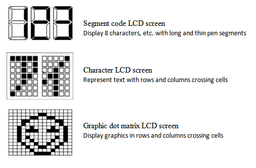
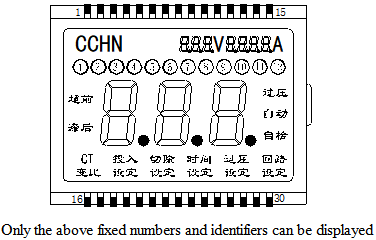
2.3.1. Digital liquid crystal display module: This is a functional component assembled by a field-type liquid crystal display and a dedicated integrated circuit. It can only display some fixed display numbers and some identification symbols. This type of LCD is generally made into TN and HTN, and STN is also used for high requirements (mainly to increase the viewing angle range). The DUTY number is generally 1/1, 1/2, 1/3, 1/4, 1/8, and the maximum can be 1/32.
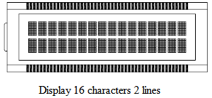
2.3.2 Character dot-matrix liquid crystal display module: it is assembled by character dot-matrix liquid crystal display, dedicated row and column drivers, controllers and necessary connectors and structural parts, and can display numbers and Western characters. This character dot matrix module itself has a character generator, which has large display capacity and rich functions. Generally, this type of module can display at least 8 characters and 1 line of characters. The dot matrix arrangement of this module is composed of groups of 5×7, 5×8 or 5×11 pixel dot matrix arrangements. LCD is generally made into TN and STN, and the DUTY number is generally more than 1/8.
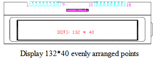
2.3.3 Graphic dot-matrix LCD module: This module is characterized by continuous and uniform arrangement of dot-matrix pixels, and there are no gaps in the arrangement of rows and columns. Therefore, a continuous and complete graph can be displayed. In addition to displaying graphics, characters can also be displayed. LCD generally uses STN, and the DUTY number is generally above 1/16.
2.4 Classification by color mode
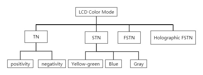
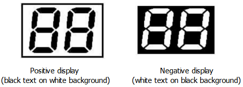
With different twist angles and polarizer angles, the LCD will have the following color modes
2.4.1 TN type classification:
A. Positivity: What is displayed is black characters on a white background.
B. Negativity: What is displayed is black and white
2.4.2 STN type classification:
A. Yellow-green mode: The yellow-green mode is displayed as a yellow-green background color, and the font is displayed in blue and black.
B. Blue mode: The blue mode is displayed as a blue background color and white font.
C. Gray mode: Gray mode is displayed as a gray-white background with dark blue fonts.
2.4.3 FSTN type classification (FSTN is to add one or two layers of compensation film on the basis of STN to compensate the interference color of STN):
A. Positivity: What is displayed is black characters on a light white background.
B. Negativity: What is displayed is white characters on a blue and black background.
2.5 Classified according to the way of light entering
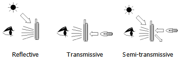
2.5.1 Reflective type: It displays by reflecting external light; the display is highly dependent on external light, and cannot be observed in a dark environment.
2.5.2 Translucent type: It can use natural light and backlight. When the external light is strong, the backlight can be used. When the external light is weak, the backlight can be used.
2.5.3 Fully transparent type: does not depend on external light, but needs a backlight.
2.6 Types of LCM - Classified from the process (according to IC packaging form)
2.6.1 Zebra strip connection: When using this connection method, it is necessary to use a structural member to fix the LCD, conductive adhesive strip and PCB board together, because the electrode spacing can be made very small, so it is suitable for products with a large number of drive channels.
2.6.2 Metal pin connection: Fix the metal pin on the outer lead of the LCD, either directly fix the LCD on the PCB, or insert the LCD into the socket of the PCB, the distance between the metal pins is 2.54mm, 2.0mm, 1.8mm , 1.5mm, 1.25mm. Applicable glass thicknesses are 1.1mm, 0.7mm, 0.55mm.
2.6.3 Zebra paper (heat-pressed paper) connection: use zebra paper to connect the LCD and PCB board together. Since the film base is soft, it is easy to fix during use and can reduce the installation thickness.
2.6.4 TAB (abbreviation for Tape Automated Bonding): It connects the soft tape with the drive circuit to the LCD through ACF (Anisotropic Conductive Film). It reduces the volume of LCM. It is a method of bonding the soft tape with the driving circuit through ACF (Anisotropic Conductive Film) and hot pressing under a certain temperature, pressure and time to realize the connection between the screen and the driving circuit board. a processing method. It mainly includes four processes of ACF preloading, alignment checking, main pressing and testing.
2.6.5 COB: COB is the English abbreviation of Chip On Board. It is another processing method of LCM drive circuit board.
The process is to directly paste the bare chip on the designated position of the PCB board with adhesive, connect the electrode of the chip with the corresponding pad of the PCB board with the aluminum wire through the welding machine, and then seal the chip and the aluminum wire with black glue and solidify. In this way, the electrical and mechanical connection between the chip and the electrodes of the circuit board is realized. The process includes seven processes of bonding, curing, pressure welding, testing, sealing, curing and testing. The COB process adopts small bare chips, and the equipment has high precision. It is used to process PCB boards with more lines, thinner gaps, and smaller area requirements. It is damaged by the outside world and has high reliability, but it cannot be repaired after damage and can only be scrapped.
2.6.6 COG: COG is the English abbreviation of Chip On Glass. It is a processing method that directly connects the LCD screen and the IC circuit.
This process is to stick the LSI-IC dedicated chip dedicated to LCD on the small area of the LCD outer lead, weld the terminals together according to the requirements with the pressure welding wire, and then cast a drop of sealing glue on it. , and the input terminal of the IC is also designed on the LCD outer lead glass, and is also pressure-welded to the input terminal of the chip. At this time, the LCD with the chip has formed a complete LCD module. Just connect it to the PCB. The process mainly includes seven processes: screen placement, ACF placement, chip placement, alignment inspection, chip bonding, glue sealing, and inspection.
2.6.7 COF: COF is the English abbreviation of Chip On Film. It is to press-weld the integrated circuit chip to a soft film transmission belt, and then use anisotropic conductive adhesive to connect the soft film transmission belt to the outer lead of the liquid crystal display device. This method is mainly used in display systems that require a small size.
2.6.8 SMT: SMT is the English abbreviation of Surface Mounted Technology. Translated as surface mount technology.
The SMT process is one of the manufacturing processes of the liquid crystal display drive circuit board (PCB board). It uses the mounting equipment to attach the mounting components (chips, resistors, capacitors, etc.) to the corresponding pad positions of the PCB board printed with solder paste. It is a processing method in which components are soldered on the PCB board through reflow equipment.
The process includes five processes of silk screen printing, placement, reflow, cleaning and testing. Due to the influence of the size (package size) of mounted components (especially chips), the number of gaps between chip pins and the accuracy of equipment, the SMT process is suitable for the processing of large-area PCB boards, and because its solder joints are exposed , highly vulnerable to damage, but easy to repair.
2.7 Backlight
Liquid crystal display device is a passive display device, which does not emit light by itself, but realizes display by modulating external light. Generally, the lighting technology of liquid crystal display is divided into natural lighting technology and backlight lighting technology. At present, the commonly used backlight sources are mainly:
2.7.1 Semiconductor light-emitting tube (LED): LED is a commonly used backlight at present, and there are two types: bottom-emitting LED and side-emitting LED.
2.7.2 Electroluminescence (EL): The shape of the lamp is very thin, which hardly increases the thickness of the LCD assembly (generally only 0.3MM thick). AC drive, the AC power is usually 70~110V 400Hz, and can be driven by peripheral chips.
2.7.3 Cold Cathode Fluorescent Lamp (CCFL): The color is generally white and the brightness is very high. An external drive is required.
2.8 Divided according to the display characteristics of the LCD screen:
2.8.1 High-brightness display screen: LCD screen display brightness above 500cd/m2, suitable for display devices that need to be visible in outdoor sunlight.
2.8.2 Full viewing angle LCD screen: It has full viewing angle characteristics, and also has high contrast, color saturation and dynamic definition.
2.8.3 Wide temperature LCD screen: suitable for places with severe temperature conditions, the working temperature and storage temperature can reach -30 ℃ to +85 ℃, and the high temperature limit of some models can reach 85 ℃.
2.8.4 Semi-reflective and semi-transparent screen: It has outstanding display effect for display devices working under strong light, and excellent reading performance in low-light and low-light environments.
2.9 According to the type of LCD panel:
2.9.1 TN liquid crystal panel: the most basic and common display mode, simple to manufacture, high transmittance, and low cost.
2.9.2 IPS panel: excellent full viewing angle characteristics, dynamic definition, color reproduction effect.
2.9.3 VA liquid crystal panel: With its advantages of wide viewing angle, high contrast and no need for rubbing alignment, it has become the first choice for large-size TFT LCD liquid crystal panels.
2.10 According to the interface type of the LCD screen: the most common interfaces are RGB interface, SPI interface, MCU interface, MIPI interface, LVDS interface, and others include HDMI interface, TTL interface, STN interface, etc.
2.11 According to the application fields of LCD liquid crystal screens: home appliance display, vehicle display, commercial display, medical display, industrial display, instrumentation, outdoor handheld and other display fields.


 Home
Home HEM LCD
  Apr 12,2023
 What is the manufacturing process of LCD?


